Showing posts with label Circuit. Show all posts

Arduino oscilloscope 22kHz bandwidth

  簡易 Arduino 示波器

    Arduino 的 ADC 是很好用的東西,可以用來測量電壓轉成數位資料,而示波器就是把隨著時間變化的電壓畫成圖形表示出來,利用 arduino 的 ADC 加上電腦的繪圖能力,作成了一個簡易示波器。

Arduino oscilloscope - flashlight waveform
做了一下功課,已經有人作了Arduino 示波器 (不靠其的的元件,只用 arduino)
窮人的示波器 - 使用 arduino 透過序列埠傳到到電腦,然後用 Processing 程式作繪圖。
Arduino – Poor Man’s Oscilloscope
http://randomnerdtutorials.com/arduino-poor-mans-oscilloscope/

arduino 接上電腦後用 Processing IDE 執行他的程式,可以看到由右往左一直捲動的波形,我有一台示波器了 :)。用10k電阻加光敏電阻做了一個測試電路來觀察波形,用手電筒的光照射產生電壓變化,得到了以上的波形,手電筒有五檔變化:強光、中光、弱光、爆閃、SOS,可以看到中光和弱光是用PWM來調整亮度的。

Arduino oscilloscope photo resistor test circuit

可惜的是原來的程式算了一下每秒大約更新 400 個點,對一個示波器來說最重要的參數就是頻寬,除了看到變化,更希望能看到細節。看了一下程式作了一些改進,首先是 Serial 的速度從 9600 提高到了115200 bps,然後每個點原來是送3個byte,改成只送1個byte,犧牲了解析度換取速度,這樣從每秒 400 個點提高到了每秒約 8300 個點,原以為這樣就是極限了,但還有更好的方式,待續 ...


LM317 8.4V Li-ion Battery Charger

自製 9V 鋰電充電器  
因新電表太耗電所以買了9V 充電電池,但某南孚環高充電器質量實在太差,沒法停止充電,只好想到自己作一個充電器
LM317 8.4V Li-ion charger 1.jpg
LITELONG 力特朗 9V 650mAh li-ion 鋰離子 充電電池 充電中 

LM317 8.4V Li-ion charger 2.jpg
9V battery plug 是從舊電池拆下來的

LM317 8.4V Li-ion charger 3.jpg
主要零件 LM317 voltage regulator

LM317 8.4V Li-ion charger_board.jpg
LM317 8.4V  li-ion battery charger circuit

LM317 8.4V  li-ion battery charger schematic


關鍵零件用的是 LM317 可調式線性穩壓器
LM317.png

http://goods.ruten.com.tw/item/show?21403122108813

LM317 用兩個電阻來調整輸出電壓(Vout=1.25V(1+R2/R1)+IadjR2),跟據datasheet 的範例 R1 的範圍從 240Ω~1.2kΩ,假設選定 R1=1k, Vout = 8.4V, 則R2 = R1(Vout - 1.25) / (1.25 + Iadj R1) = 5.296kΩ,因為手邊只有 50k 可變電阻,所以拿它與 6.8k 並聯成 為 R2,電阻範圍從 0Ω~ 5.99kΩ,

VR 5.99.png
6.8k與50k可變電阻並聯

得到可調電壓 Vout 從 1.25V 到 8.733V,完成後可以用電表測量,調整輸出電壓在 8.3V~8.4V左右。


鋰電池充電需要的是定電流及定電壓,
constant current constant voltage.jpg

Current Limited 6V Charger.png


參考datasheet範例,利用一個NPN電晶體及電流感測電阻,設定電流為0.6/R,當電流增大,使得電阻上的電壓大於0.6時,使得電晶體導通,ADJ 電位下降導致 Vout 下降,然後電流就可以維持在設定的範圍內。照片上目前只放了一個5Ω電阻,所以輸出是 120mA功率為 0.6V * 0.12A = 0.072W,所以 1/4 瓦的電阻還夠用


電源指示燈
LM317 有最小負載電流的需求用來維持晶片的運作,約 3.5~10mA,一般是利用設定電壓電阻來順便達成(例:R1 選用 240 Ω),這裡因為選用的電阻較大R1=1k, R2=5.29k,  8.4V / 6.29k = 1.33 mA,所以在輸出上加一個LED燈,剛好維持住最小負載電流。
http://electronics.stackexchange.com/questions/18524/resistors-values-to-use-with-lm317


充電電流指示燈
利用二極體及電阻的分流達成了在充電一開始時較亮,然後隨著充電電流變小時慢慢變暗,在電流小於10mA左右熄滅,就可以得知充電完成

散熱
如果長時間輸出 120mA 以上的話,LM317 最好要有散熱片

超便宜測量電感的方法 Inexpensive measuring inductance with arduino

   一般要量測電感需要專用的 LCR 電錶或是用示波器,都不便宜,在網路上找到這篇
https://reibot.org/2011/07/19/measuring-inductance/ ,
使用 arduino 加上一個極簡單的電路達成,
關鍵的元件只有三個:
一個電壓比較器或 op amp、
兩個 1uF 無極性電容、
以及一台 arduino 相容板。

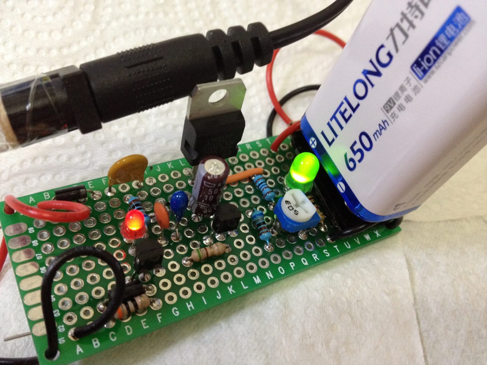
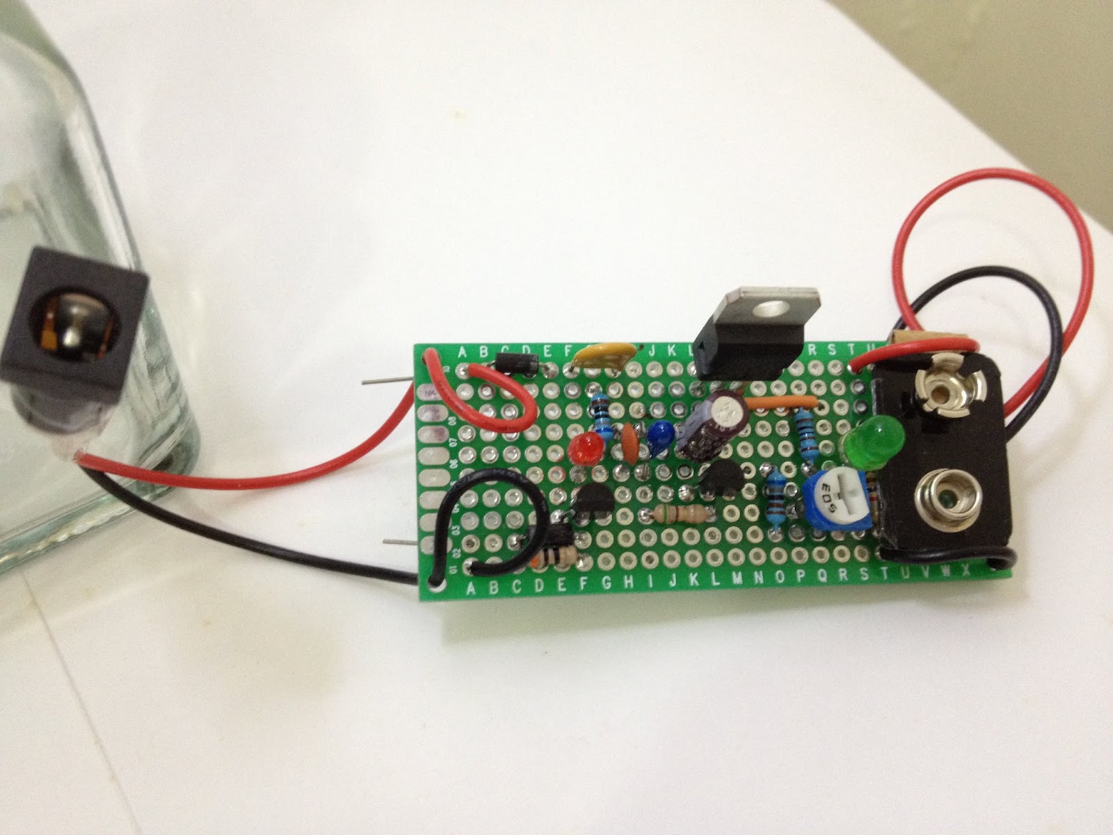
我用的是 LM393P 低功耗電壓比較器 $2
http://goods.ruten.com.tw/item/show?21403134960362

陶瓷電容 1uF(105) $0.8
http://goods.ruten.com.tw/item/show?21439300127596
或是用較小的並䏈
陶瓷電容 0.1uF(104) $8
http://goods.ruten.com.tw/item/show?21601579393657


電路圖

Measuring inductance with arduino
程式
// resonant frequency counting for inductance measuring
#define chargePin 13
#define pulsePin 11
void setup() {
  Serial.begin(115200);
  pinMode(pulsePin, INPUT);
  pinMode(chargePin, OUTPUT);
  Serial.println("LC Meter");
}
double pulse, frequency, inductance;
void loop() {
digitalWrite(chargePin, HIGH); // charge LC circuit.
delay(5);
digitalWrite(chargePin, LOW);
//
pulse = pulseIn(pulsePin, HIGH, 1000); //returns 0 if timeout
if (pulse > 0.1) {
 const double capacitance = 1.89E-6; // ~2 uF
 frequency = 1E6 / (2 * pulse);
 inductance = 1E6 / ( 4 * 3.1415926535 * 3.1415926535 * capacitance * frequency * frequency );
 Serial.print( int(pulse) );
 Serial.print(" uS, ");
 Serial.print( frequency );
 Serial.print(" Hz, ");
 Serial.print( inductance );
 Serial.println(" uH");
}
delay(480);
}
// end

原理:
當LC電路放電時,會震盪產生一個頻率,叫 resonant frequency
f = 1/(2π√LC)
https://en.wikipedia.org/wiki/LC_circuit

已知電容和頻率就可以算出電感
L =  1 / (4C π^2 f^2)

arduino 測量頻率的方法:
LC 的信號經過比較器後變成 0~5V 的方波(大於零變5V 小於零變 0V)
arduino 的 pluseIn() 可以測量信號在 HIGH 的時間

所以 頻率 f = 1 / ( 2 * pluseIn() 時間)

我的兩個1uF電容量測起來約 ~1.89 uF,使用較小的電容時因為頻率會上升,
arduino 的限制無法量到更小的時間 (10^-6),如果要量較小的電感,需要較大的電容,
用 1.89uF 實測可以量到 10 uH 以上。


Li-ion emergency light circuit with low voltage cutoff protection

Emergency light circuit with low voltage protection.


Emergency light and low voltage cutoff circuit 

Using forward voltage drop of LED to protect lithium ion battery from getting too low.
The light will be cutoff around 3 volts.
The upper limit voltage of eight chip LED is higher than battery, no need to add current limit resistor.


Emergency Light NPN PNP 1W LED Low Voltage Protection

Emergency light npn pnp perfboard


Emergency light npn pnp usb power two led


Emergency light npn pnp 18650 li-ion two led ON


Emergency light circuit


Emergency light circuit using NPN transistors & 1W LED

Emergency light circuit  NPN
1W 300~350mA LED  (or multiple LEDs in parallel)
Cell phone Li-ion battery 3.7V
USB 5V power
S8050 NPN  20V 700mA transistor control LED current
Adjustable brightness
Charge current indicator LED
Minimum standby current


Emergency light circuit
Simplified version

Choice of R1 for LED
20mA  40k
40mA  20k
60mA  13.3k
80mA  10k
100mA 8k
200mA 4k
300mA 2.6k


Emergency light circuit PNP